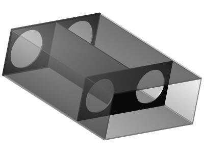
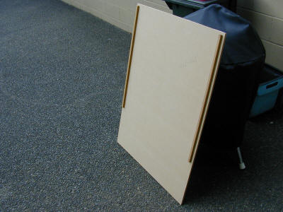
The Mirror Box
This is just a simple rectangular box with a central divider and a baffle near the rear. It will have the two rotating tops fitted to the top end with the main mirrors in the open bottom end. I may yet cut large holes in the top and sides to remove weight. The face that's closest to the user will stay solid to reduce body heat affecting the image. Man this isn't going to be pretty, just functional !
It has taken about six hours to get to this stage. Two hours marking out and on the saw bench. It's important when making a box to get everything the same size and parallel. I ran the three central dividers and a brace and the lower baffle through the saw at 300mm wide all at the same time so they have to be all the same width. Any time you have several pieces the same width or length always cut them together to get them exactly the same.
I started with the two largest pieces slightly to big by about 4mm on each edge. This is so that I could glue them up with an overhang then trim them back with a plane or router afterwards. I glued and nailed two corner braces exactly 730 (finished width) minus 18mm (thickness of two 9mm sides) or 712 apart on their outside edges. I did this on both front and back sheets and left to dry overnight.
In this picture you see the bottom, two sides, the middle baffle and nearest me a gluing brace board. This board is only used as a brace during gluing to keep things square so don't get any glue on it !
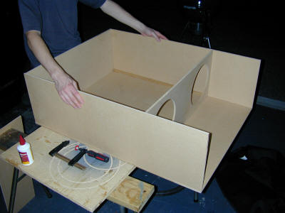
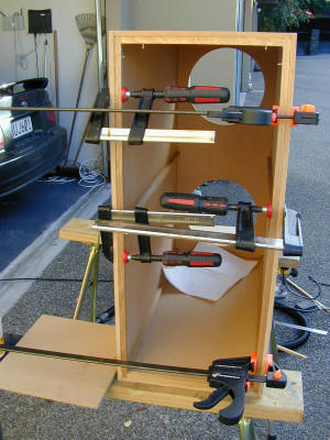
I found it easiest to glue with things on the side, here I'm just putting glue on ready to accept one of the sides. The middle baffle and the front brace board are keeping everything square.
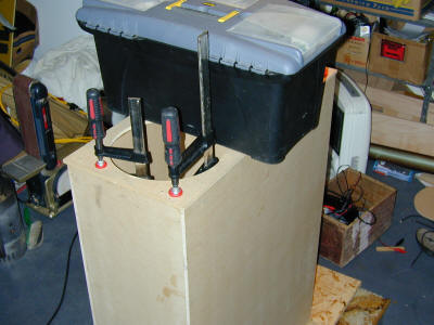
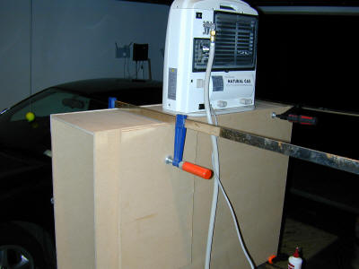
A few handy objects used as weight to get everything to fit. The clamps I had aren't big enough to go side to side, so gravity was used instead
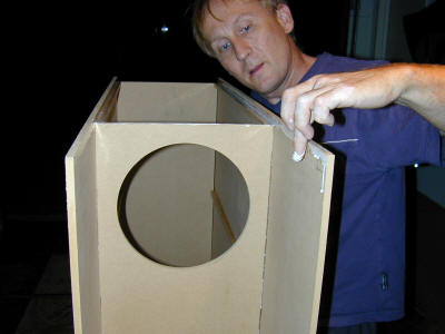
Gluing some corner braces to the front face ready for the front board to go on, note the brace board is now gone.
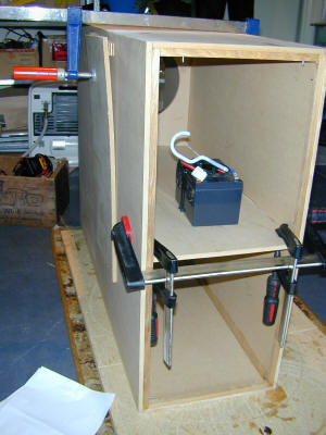
The middle divider in place being glued in.
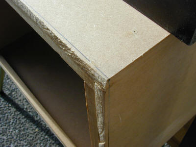
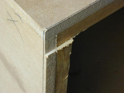
The edges aren't very square or even and I need to glue on the top board for the UTA's to fit into so I needed to do some trimming.
I marked around the outside with a large square then got out my big piece of angle aluminium to act as a router guide. Note the wooden router width guide which is already the exact width of the router cut, I just line this up with my pencil line and the aluminium guide is in the right place for routing the edge.
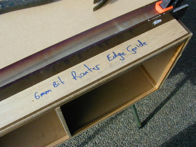
One edge done just a few to go.
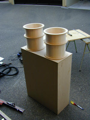
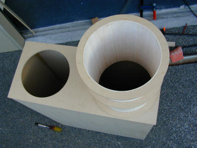
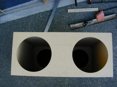
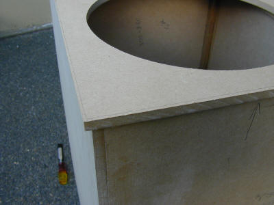
The holes in the top are cut to be exactly 1mm larger than the UTA this is about the only precision part in the whole telescope. Get it to small and it won't rotate to big and the UTA will slop about. I of course cut a test hole and tried the UTA's in it first to get the correct size.
Notice how the top overlaps a bit just like the sides did before so they can be trimmed off with a router later
The bits just sitting together for the first time just because I could
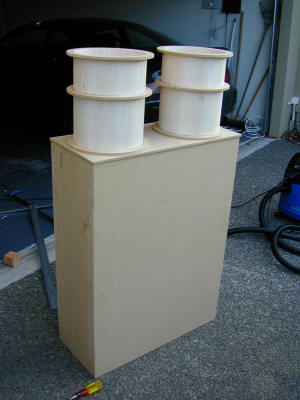
The top gets glued on